- Products
- All Products
- RF PA Extension Kit
- Wireless Microphone Upgrade Packs
- In-Ear Monitor Upgrade Packs
- Wireless Microphone Antennas
- Wireless In-Ear Monitor Antennas
- Antenna Distribution for Microphones
- Antenna Combiners for In-Ear Monitors
- Multi-Zone Antenna Combiners
- Spectrum Tools
- Accessories, Cables and Parts
- Solutions by Venue
- Resources & Training
- Performance Tools
- About Us
December 14, 2014
Take a Bite out of Interference with "Shark Fin" LPDA Antennas
Written by: Alex Milne

Directional antennas for wireless microphones have a tough job. Not only do they provide moderately high gain and good rejection from interfering signals in a compact size, but they need to do so over a very wide band, 470-698 MHz. While many different designs are capable of this, for many years the most popular design has been the triangle shaped UHF LPDA antenna.
LPDAs, also known as shark fin antennas, were first built by a group of engineers in the late 50s at the University of Illinois “Antenna Lab.” They were researching designs that could accommodate larger bandwidths without appreciably increasing the size of an antenna. They found a surprisingly simple construction of individual dipole elements spaced along a rod logarithmically based on the difference between each dipole tooth (hence a logarithmic periodic dipole array, or “LPDA”) gave excellent performance over a wide frequency range.
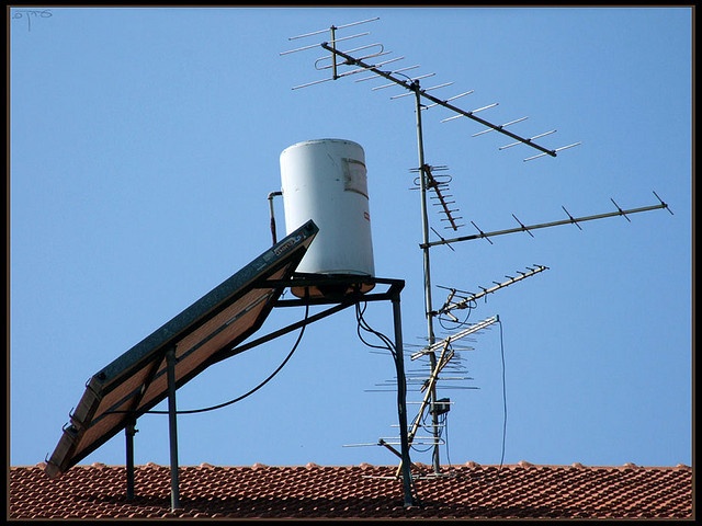
The LPDA was quickly adopted for wideband UHF and VHF TV band use, among other things. The rooftop TV receivers still seen today are often LPDA, sometimes alongside their less compact cousin, the Yagi antenna. Since wireless microphones operate in the TV white space, UHF LPDAs are a natural choice for a directional antenna of modest expense.

LPDA and Yagi antennas on a rooftop in Israel. Photo Courtesy Erin Fickle.
Most of the major microphone manufacturers offer this type of antenna as a common external accessory. They might be billed as shark fins, or paddle antennas, but open them up and you’ll find a good ole’ LPDA inside, usually printed from conductive material on a circuit board instead of made from wire or metal bars. Virtually all pro sound segments use them, from live sound, to broadcast, film, and installed sound.
For best performance, they are deployed in matched pairs for use with diversity receivers. Spacing two paddles apart by a 1/4 wave or more gives good directionality as well as reduction of multi-path interference. They can also be orientated for vertical or horizontal polarization, depending on the polarization of the transmitting antenna.
Leading image courtesy Travelbag.
Tag(s):
Knowledge Guides
Alex Milne
Alex Milne was Product Marketing Manager and Digital Marketing Manager for RF Venue, and a writer for the RF Venue Blog, from 2014-2017. He is founder and CEO of Terraband, Inc., a networking and ICT infrastructure company based in Brooklyn, NY., and blogs on spectrum management, and other topics where technology,...
More from the blog

2.4 GHz CP Beam
RF Venue Antennas Support Times Square Musical Festival
1 min read
| December 15, 2014
Read More

CP Beam Antenna
Basics of Wave Polarization Explained
4 min read
| December 15, 2014
Read More

Knowledge Guides
The Myth of Half-wave Diversity Antenna Placement
6 min read
| December 15, 2014
Read More
Subscribe to email updates
Stay up-to-date on what's happening at this blog and get additional content about the benefits of subscribing.

