How well your RF system handles signals — from antenna to receiver for wireless mics, or from IEM transmitter to antenna — will play a great role in how reliable and good-sounding your wireless audio will be.
We want our RF systems to convey the desired RF signal or signals without adding noise or distortion. That’s not too different from our goals for most audio equipment. But noise and distortion in audio circuitry have directly audible effects, while in RF circuitry they can blank out signals or cause interference.
The need for low noise is easy to understand; signals buried in noise are difficult to receive and demodulate cleanly. In fact, we want our signals to arrive at the receiver at least about 20 dB above the noise floor (both the ambient RF noise environment plus any noise produced in active electronics, such as a distro or combiner), and certainly away from any over-the-air DTV broadcast signals. The need for headroom — that is, a high range of linearity — is less obvious to the casual observer.
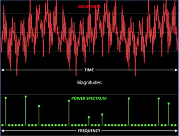
A linear circuit will pass multiple simultaneous signals cleanly. The carriers will coexist without influencing each other and the receivers will collect their respective signals easily. In a nonlinear circuit, though, those signals will intermodulate with each other, producing artifact signals that raise the noise floor and may directly interfere with the signals of our mics or IEMs.
Small-signal RF amplifiers are often constructed around single-ended transistor circuits with a transfer function similar to Figure 2. The transfer function is curved, not linear, but small signals will occupy a small portion of the curve that approximates a straight line, while larger signals will increasingly have their waveforms bent according to the curve. Think of it as analogous to the Earth being round, but in our immediate vicinity, it’s flat.
This nonlinearity causes distortion when there are stronger signals, which is generally not problematic for a single signal or even two, but three or more will produce intermodulation distortion, or IMD. In a nonlinear circuit, the possible IMD products will grow exponentially with the number of RF signals.
This is a perfect argument for what I call the three-pronged defense against intermodulation:
- Frequency coordination This is Job 1 for assembling any wireless audio system of three or more channels. You must coordinate not only mics and IEMs, but all wireless signals in your production or event, including wireless guitar rigs, wireless intercoms, et al.
- High dynamic range Any active circuitry in your RF signal path should have high dynamic range — that is, very low noise and high headroom, with a highly linear operating range in between.
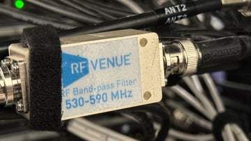
- Bandpass filtering Any wireless mic receiving system will benefit from appropriate filtering in the A and B antenna feeds to the distro inputs. No one ever regrets bandpass filtering their mic system! For more information, see my blog on bandpass filters.
Bob Lee
Bob Lee is an application engineer and trainer at RF Venue, Inc., having worked in pro audio and broadcasting for more than four decades. Bob started doing live theatre sound in 1980 with analog boards and area mics, because only the biggest theatre companies had wireless back then. He designed and serviced wireless...
More from the blog
Subscribe to email updates
Stay up-to-date on what's happening at this blog and get additional content about the benefits of subscribing.


